Bracing style | - This setting selects how the structure will be braced. The option affects the calculation of the out-of-plane buckling on the top chords. The following options are available: "Type A - bracing using loose timber" represents the bracing of the top chords with diagonal timber braces on the underside of the chords, "Type B - bracing frames" corresponds to the use of bracing trusses in the roof plane, and "Type C - gable trusses connected to the wall" is used in cases where the gable truss is continuously connected to the gable wall. If option "A" or "not specified" is selected, the maximum of the batten distance and the centreline distance of the trusses shall be considered as the buckling length of the top chords for the out-of-plane buckling calculation. If option "B" or "C" is selected, the out-of-plane buckling length shall always be the battening distance.
|
Compressive forces in joints | - The option to set how the distribution of compressive forces in the connections will be handled. There are several options for the force splitting between the nail plates and the contact of the timber elements. The most effective option is the "split compressive force automatically" option, which assigns the maximum compressive force to the contact between the timber elements and the rest is used for the design of the nail plate.
|
Structural model | - In this option, it is possible to select a structural model which will be used for calculation of internal forces.. There are two options to choose from: the "NF DTU 31.3" option creates the structural model according to the French standard NF DTU 31.3 part 3. In the "DIN EN 1995-1-1" option, the structural model is created according to the German national annex and related documents.
|
Connections (ULS) | - This option allows user to set the connection style when calculating the internal forces for the ultimate limit state. When selecting the connection type, the standard provisions (e.g. EN 1995-1-1, section 5.4.2) should be respected. Some national annexes to EN 1995-1-1 provide detailed rules, so the range of options may be limited.
|
Connections (SLS) | - This option allows you to set the way the connections are modelled when calculating deformations for the serviceability limit state. The only option that takes into account the slip of the connections directly in the calculation is "spring connection".
|
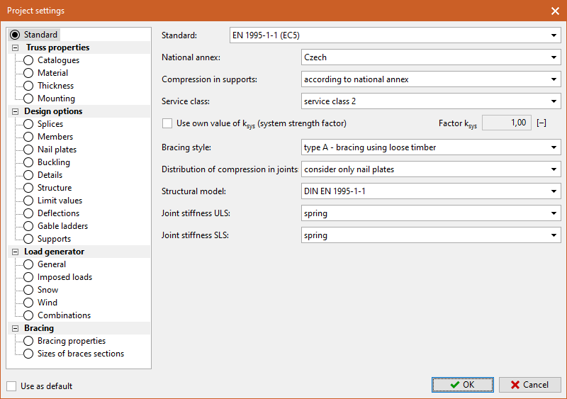 Tab "Standard"